Identifying Common Missteps in Mechanical Design Practices
10 October 2024
How Contract Machining Can Boost Your CNC Machining Business
18 October 2024Programming plays a crucial role in CNC machining, directly impacting its quality and efficiency. Many people have a love-hate relationship with programming. How can we quickly master CNC machining center programming skills?
Pause command
G04X (U) _/P_ is used to indicate the tool pause time. When this code is executed, the feed stops but the spindle continues to run. The value that comes after the P or X address represents the pause time. If the value comes after X, it must include a decimal point; otherwise, it is interpreted as one-thousandth of that value in seconds (s). If the value comes after P, it must be an integer and is interpreted as the pause time in milliseconds (ms).
In some hole processing instructions, like G82, G88, and G89, a pause time is needed when the tool reaches the bottom of the hole to ensure the roughness of the hole bottom. During this time, only address P can be used to represent it. If address X is used instead, the control system will interpret X as the X-axis coordinate value for execution.
Differences and connections between M00, M01, M02 and M03
M00 is an unconditional pause instruction for the program. When the program reaches this point, the feed and spindle stop. To restart the program, you must first return to the JOG state, press CW (spindle forward) to start the spindle, then return to the AUTO state, and press the START key to start the program.
M01 is a selective pause instruction for the program. Before the program is executed, the OPSTOP key on the control panel must be turned on. The effect after execution is the same as M00. To restart the program, follow the same steps as for M00. M00 and M01 are often used to inspect the size of workpieces or remove chips during processing.
M02 is the main program end instruction. When this instruction is executed, the feed, spindle, and coolant are turned off, but the program cursor stops at the end of the program.
M30 is also a main program end instruction. Its function is the same as M02, but the cursor returns to the program header position, regardless of whether there are other program segments after M30.
The meanings of addresses D and H are the same.
The parameters D and H for tool compensation serve the same function and can be used interchangeably. They both correspond to the names of compensation registers in the CNC system. However, the specific compensation value is determined by the compensation number address associated with them. In a machining center, to avoid errors, H is typically designated as the tool length compensation address, with compensation numbers ranging from 1 to 20. Meanwhile, D is specified as the tool radius compensation address, with compensation numbers starting from 21 (in cases where a tool magazine contains 20 tools).
Mirror instructions
When only the X-axis or Y-axis is mirrored, the cutting sequence (down prototype CNC milling and reverse prototype CNC milling), tool compensation direction, and circular interpolation direction during cutting will be opposite to the actual program. However, when both the X-axis and Y-axis are mirrored at the same time, the cutting sequence, tool compensation direction, and circular interpolation direction will remain unchanged.
Note: After using the mirror instruction, it is necessary to use the M23 command to cancel it in order to avoid affecting the subsequent program. When in G90 mode and using the mirror or cancel instruction, it is important to return to the origin of the workpiece coordinate system before using it. Failure to do so will result in the CNC system being unable to calculate the subsequent motion trajectory, causing the tool to move randomly. In such cases, a manual origin return operation must be performed to resolve the issue. It's important to note that the spindle direction does not change with the mirror command.
Arc interpolation command
G02 is used for clockwise interpolation, while G03 is used for counterclockwise interpolation. In the XY plane, the format is as follows: G02/G03 X_Y I_K F_ or G02/G03 X_Y R F_, where X and Y are the coordinates of the arc endpoint, I and J are the incremental values from the arc start point to the center on the X and Y axes, R is the arc radius, and F is the feed rate.
When cutting an arc, please note that if q≤180°, R is a positive value; if q>180°, R is a negative value. I and K can also be specified by R. When both are specified at the same time, the R command takes precedence, and I and K are invalid. R cannot be used for full-circle cutting. Full circle cutting can only be programmed with I, J, and K because there are countless circles with the same radius passing through the same point. When I and K are zero, they can be omitted. Regardless of whether G90 or G91 mode is used, I, J, and K are programmed according to relative coordinates. During circular interpolation, tool compensation instructions G41/G42 cannot be used.
Advantages and disadvantages between G92 and G54~G59
Coordinates G54 to G59 are set before processing, whereas G92 is set within the program. If G54 to G59 are in use, there's no need to use G92 again. However, if G54 to G59 are replaced, G92 should be avoided. Note: (1) Once G92 sets the coordinate system, using G54 to G59 again won't have any effect unless the power is turned off and the system is restarted, or G92 is used to set the new prototype machined parts coordinate system. (2) After the program using G92 ends, if the machine tool doesn't return to the origin set by G92, starting the program again will make the current position of the machine tool the new workpiece coordinate origin, which can lead to accidents.
Programming tool change subroutine
In machining centers, tool changes are inevitable. However, the machine comes with a fixed tool change position set at the factory. If the machine is not at this position, the tool cannot be changed. Additionally, certain conditions must be met before a tool change, including canceling tool compensation and cycle, stopping the spindle, and turning off the coolant. These prerequisites, if managed manually for each tool change, can lead to errors and inefficiencies. To streamline this process, a tool change program can be developed and saved, allowing operators to execute it automatically via M98, ensuring a smooth and error-free tool change.
Taking the PMC-10V20 machining center as an example, the program is as follows:
O2002;(Program name)
G80G40G49;(Cancel fixed cycle, tool compensation)
M05;(Spindle stop)
M09;(Coolant off)
G91G30Z0;(Z axis returns to the second origin, i.e. tool change point)
M06;(Tool change)
M99;(Subprogram ends)
When a tool change is needed, just type "T5M98P2002" in the MDI state to replace the required tool T5, thus avoiding many unnecessary mistakes. Readers can compile corresponding tool change subprograms according to the characteristics of their own machine tools.
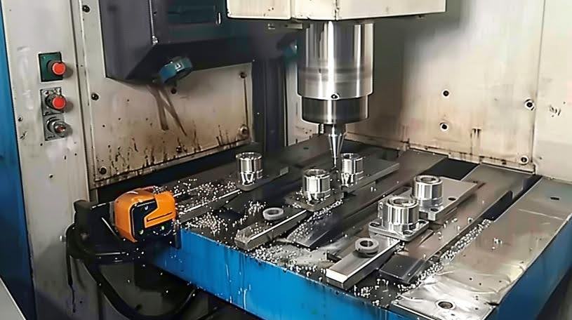
Recommended design with thread clearance holes
Others
The program segment sequence number is designated by the address 'N'. Since the memory space in CNC devices is typically limited, sequence numbers are often omitted to conserve storage. The 'N' value serves solely as a reference for locating and editing program segments and does not impact the CNC machining process. Sequence numbers can be incremented or decremented, and continuity is not required. However, they are essential when utilizing certain loops, jump, subroutine calls, and mirroring instructions. In a single program segment, if identical instructions or groups of instructions are present, only the latest will be executed.
If you wanna know more, please feel free to contact [email protected]
Anebon team's specialty and service consciousness have helped the company gain an excellent reputation among customers worldwide for offering affordable CNC machining parts, CNC prototype machined parts, and CNC lathe machining parts. The primary objective of Anebon is to help customers achieve their goals. The company has been making tremendous efforts to create a win-win situation for all and welcomes you to join them.

