The Comprehensive Guide to Stamping Bar in Manufacturing
25 June 2024
A Comprehensive Guide to CNC Turning Machine Parts
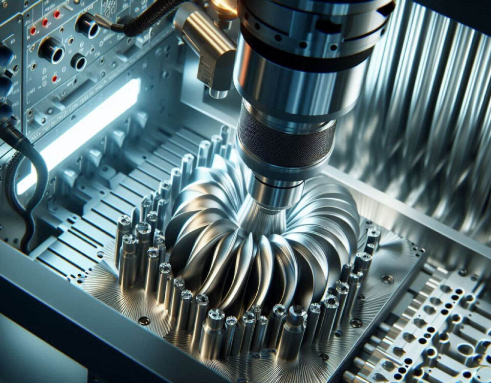
28 June 2024Five-axis machining, also known as 5-axis machining, is a type of CNC machine tool processing. It involves the simultaneous linear interpolation motion of five coordinates: X, Y, Z, A, B, and C. The machine tools used for five-axis machining are typically referred to as five-axis machine tools or five-axis machining centers.
But do you really understand five-axis machining?
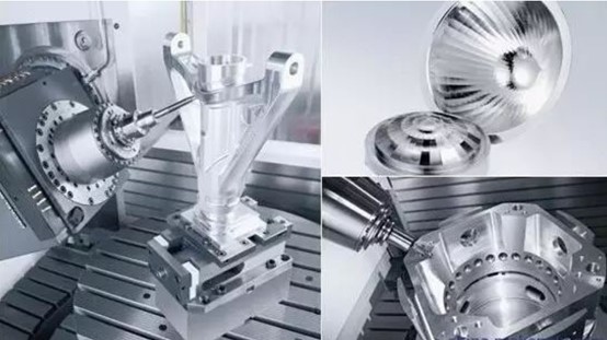
Development of five-axis technology
For many years, it was widely believed that five-axis CNC machining technology was the only way to process continuous, smooth, and complex surfaces. When faced with challenges in designing and manufacturing complex surfaces, people turned to five-axis machining technology.
Five-axis linkage CNC is the most challenging and commonly used technology in CNC machining. It combines computer control, high-performance servo drive, and precision machining technology to efficiently, precisely, and automatically machine complex surfaces. Internationally, five-axis linkage CNC technology is seen as a symbol of a country's level of automation technology in production equipment. Due to its special status and significant influence on industries such as aviation, aerospace, and military, as well as its technical complexity, Western industrialized countries have always enforced an export license system for five-axis CNC systems as strategic materials.
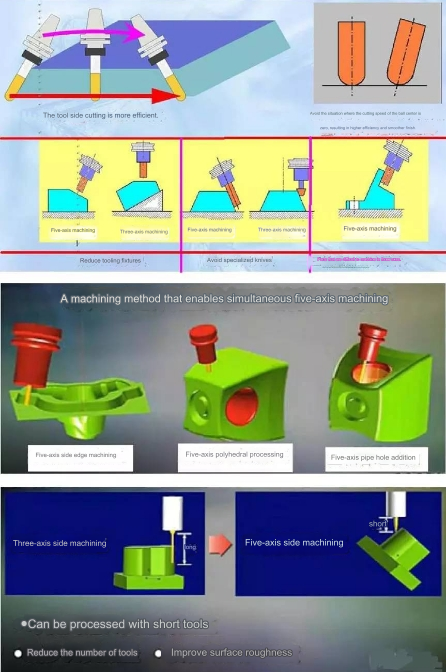
Compared with three-axis linkage CNC machining, from the perspective of process and programming, the use of five-axis CNC machining for complex surfaces has the following advantages:
- Improve machining quality and efficiency
- Expand the process range
- Meet the new direction of composite development
However, due to interference and tool position control in the processing space, the CNC programming, CNC system, and machine tool structure of five-axis CNC machining are much more complicated than three-axis machine tools. Therefore, the five-axis is easy to say, but it isn't easy to realize it! In addition, it is even more difficult to operate and use it well!
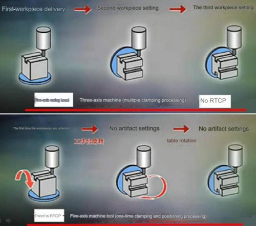
When it comes to the five-axis, it's important to distinguish between real and fake five-axis. The main difference lies in whether there is an RTCP function. RTCP stands for "Rotational Tool Center Point" and refers to the tool rotating around the center point. Different manufacturers have their own names for similar technology, such as TCPM or TCPC.
With Fidia's RTCP, if the RTCP function is executed manually, the tool center point and the actual contact point between the tool and the workpiece surface will remain unchanged.
The tool holder will rotate around the tool center point. In order to achieve this, real-time compensation for the offset of the linear coordinates of the tool center point is necessary to allow the tool holder to rotate around the target trajectory point.
This ensures that the angle between the tool holder and the normal line at the actual contact point can be changed while keeping the tool center point and the actual contact point between the tool and the workpiece surface unchanged. This is important for optimizing cutting efficiency and avoiding interference for ball-end tools. Therefore, RTCP is mainly focused on dealing with changes in rotating coordinates while standing on the tool center point.
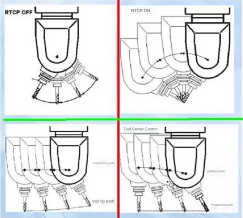
Five-axis machine tools and CNC systems without RTCP (Rotary Tool Center Point) must rely on CAM programming and post-processing, and the tool path must be planned in advance. If the machine tool or the tool is changed for the same part, CAM programming and post-processing must be re-performed. This makes the machine a fake five-axis. Many domestic five-axis CNC machine tools and systems fall under this category. Although they may insist on calling themselves five-axis linkage, they are not true five-axis systems.
Generally, there are two types of five-axis machine tools: five-axis linkage, where all five axes can be linked at the same time, and five-axis positioning processing, which is essentially five-axis three-linkage. In five-axis positioning cnc machining process, two rotary axes are rotated and positioned, and only three axes can be linked at the same time. This type of machine tool is commonly known as the 3+2 mode and is also considered a fake five-axis system.
The current form of five-axis CNC machine tools
In the mechanical design of 5-axis machining centers, machine tool manufacturers have always been dedicated to developing new motion modes to meet various requirements. Comprehensively considering the various types of five-axis machine tools on the market, although their mechanical structures are diverse, they mainly include the following forms:
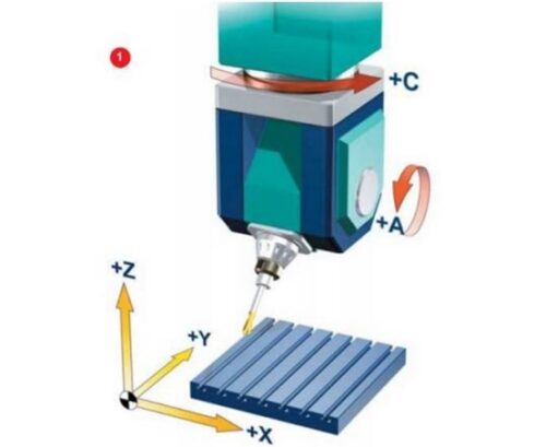
Two rotation coordinates directly control the direction of the tool axis (double swing head form)
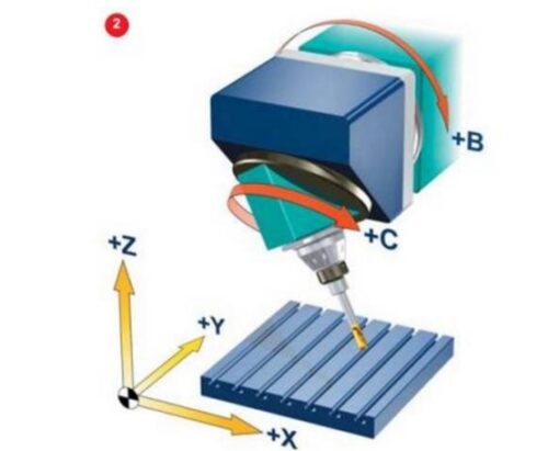
The two coordinate axes are at the top of the tool, but the rotation axis is not perpendicular to the linear axis (pitch-type swing head type)
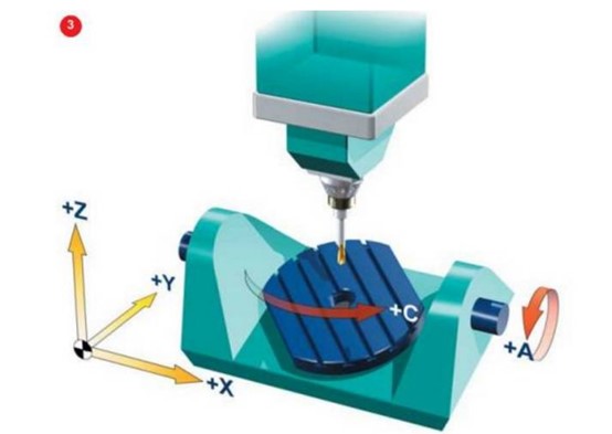
Two rotation coordinates directly control the rotation of space (double turntable form)
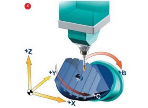
Two coordinate axes are on the workbench, but the rotation axis is not perpendicular to the linear axis (push-down workbench type)
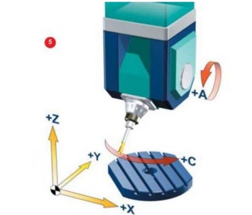
One of the two rotating coordinates affects the tool, while the other affects the workpiece (resulting in one swing and one rotation). After observing these structures of five-axis machine tools, we can gain an understanding of how the five-axis machine tool operates.
Difficulties and obstacles in developing five-axis CNC technology
The superiority and importance of five-axis CNC technology have long been acknowledged. However, its application remains limited to a few well-funded departments, and there are still unresolved issues that need attention.
Five-axis CNC programming is abstract and difficult to operate.
The challenge faced by traditional CNC programmers is the difference between three-axis and five-axis machine tools. While three-axis machines have linear coordinate axes, five-axis machines come in various forms, and the same NC code cannot always be applied to different five-axis machines. In addition to linear motion, CNC programming also involves coordinating rotational motion calculations such as rotation angle stroke inspection, nonlinear error verification, and tool rotation motion calculation. This makes CNC programming complex and abstract due to the large amount of information involved.
The operation and programming skills of five-axis CNC machining are closely intertwined. If special functions are added to the machine tool, programming, and operation become more complex. Mastery of the necessary knowledge and skills can only be achieved through repeated practice by programmers and operators. The demand for experienced professionals is a major barrier to the widespread adoption of five-axis CNC technology.
Many domestic manufacturers have bought five-axis CNC machine tools from overseas. However, due to insufficient technical training and services, achieving the full functionality of five-axis CNC machine tools is challenging, resulting in lower machine tool utilization rates. In many cases, using three-axis machine tools is preferable.
Strict requirements apply to NC interpolation controllers and servo drive systems.
The movement of five-axis machine tools combines the movement of five-coordinate axes. The addition of rotating coordinates not only increases the complexity of interpolation operations but also introduces slight errors, which significantly reduces machining accuracy. Therefore, the controller must have higher calculation accuracy.
The motion characteristics of five-axis machine tools necessitate that the servo drive system possesses excellent dynamic characteristics and a wide speed regulation range.
NC program verification is particularly important for five-axis CNC.
In order to improve machining efficiency, it is crucial to eliminate the traditional "trial cutting" verification method. In five-axis CNC machining, the verification of NC programs has become very important due to the high cost of workpieces processed by these machines. Collisions are a common problem in five-axis CNC machining, including tool cutting into the workpiece, tool collision with the workpiece at high speed, tool collision with the machine tool, fixtures, and other equipment within the processing range, as well as collisions between moving and fixed parts on the machine tool. Predicting collisions in five-axis CNC is difficult, so the verification program must comprehensively analyze the machine tool kinematics and control system.
If the CAM system detects an error, the tool path can be immediately edited. However, in the case of an NC program error during machining, the tool path cannot be directly modified as it can be in three-axis CNC. On a three-axis machine tool, the machine operator can directly modify parameters such as the tool radius. In five-axis machining, the situation is more complex because changes in tool size and position directly affect the subsequent rotational motion trajectory.
Tool radius compensation
In a five-axis NC program, tool length compensation is still available, but tool radius compensation is not supported. When using a cylindrical milling cutter for contact milling, different programs must be created for tools of varying diameters. Currently, popular CNC systems are unable to perform tool radius compensation due to insufficient data in the ISO file for recalculating the tool position. This necessitates frequent tool changes or adjustments to the tool size during CNC machining. According to standard processing procedures, the tool path should be returned to the CAM system for recalculation, which could improve the overall efficiency of the machining process.
Norwegian researchers are currently working on a temporary solution called LCOPS (Low-Cost Optimized Production Strategy) to tackle this issue. The CNC application transmits the necessary data for tool path correction to the CAM system, which then sends the calculated tool path directly to the controller. LCOPS requires a third-party CAM software that can be connected directly to the CNC machine tool, with the CAM system file being transmitted instead of ISO code. The long-term solution to this problem involves the development of a new generation of CNC control systems that can recognize workpiece model files in common formats (such as STEP, etc.) or CAD system files.
Postprocessor
The primary distinction between a five-axis machine tool and a three-axis machine tool is the presence of two rotating coordinates. The tool position needs to be converted from the workpiece coordinate system to the machine tool coordinate system, which necessitates multiple coordinate transformations. When using the widely available postprocessor generator, you only need to input the basic parameters of the machine tool to create a postprocessor for a three-axis CNC machine tool. However, for five-axis CNC machine tools, only a few enhanced postprocessors are currently available. Further development is required for postprocessors designed for five-axis CNC machine tools.
When the three axes are linked, the tool trajectory doesn't need to account for the position of the workpiece origin on the machine tool table. The postprocessor can automatically manage the relationship between the workpiece coordinate system and the machine tool coordinate system. In contrast, for five-axis linkage, such as when working on a horizontal cnc machining milling machine with five axes (X, Y, Z, B, and C), the position size of the workpiece on the C turntable and the position size between the B and C turntables must be considered when generating the tool trajectory. Workers usually spend a significant amount of time managing these position relationships when clamping workpieces. If the postprocessor can handle this data, the installation of the workpiece and the processing of the tool path will be greatly simplified. Workers can simply clamp the workpiece on the worktable, measure the position and orientation of the workpiece coordinate system, input this data into the postprocessor, and post-process the tool path to obtain the appropriate NC program.
Nonlinear error and singularity problem
Due to the introduction of rotating coordinates, the kinematics of five-axis CNC machine tools is much more complicated than that of three-axis machine tools. The first problem related to rotation is nonlinear error. The nonlinear error should be attributed to a programming error, which can be controlled by reducing the step size. In the pre-calculation stage, the programmer cannot know the size of the nonlinear error. Only after the machine tool program is generated by the post-processor can the nonlinear error be calculated. Tool path linearization can solve this problem. Some control systems can linearize the tool path while machining, but linearization is usually performed in the post-processor.
Another problem caused by the rotating axis is singularity. If the singularity point is at the extreme position of the rotating axis, any small oscillation near the singularity point will cause the rotating axis to flip 180°, which is quite dangerous.
Requirements for CAD/CAM system
For the operation of pentahedron machining, users must rely on mature CAD/CAM systems, and experienced programmers must operate the CAD/CAM system.
Large investment in machine tool purchase
In the past, there was a significant price gap between five-axis and three-axis machine tools. However, nowadays, the cost of a three-axis machine tool with an additional rotary axis is nearly the same as that of a standard three-axis machine tool. This enhanced machine tool can perform the functions of a multi-axis machine tool. Furthermore, the price of a five-axis machine tool is only 30% to 50% higher than that of a three-axis machine tool.
Apart from the machine tool investment, upgrading the CAD/CAM system software and post-processor is necessary to meet the demands of 5 axis cnc machining. It's also essential to update the calibration program to enable the complete machine tool simulation.
Future intelligent trends in five-axis machining machine tools
The control mode and human-machine interface of intelligent equipment are undergoing significant changes. With the improvement of network performance, such as WiFi broadband and Bluetooth short-range communication, mobile control methods based on networks, such as tablet computers, mobile phones, and wearable devices, are becoming increasingly popular.
Touch screens and multi-touch graphical human-machine interfaces are gradually replacing buttons, switches, mice, and keyboards. People, especially the younger generation, have become accustomed to operating smart electronic consumer products and can quickly respond, switch screens, and upload or download data. This greatly enriches the content of human-computer interaction and significantly reduces the rate of error in operations.

