Effective Methods to Address Tool Wear and Breakage
3 October 2024
Enhancing CNC Machining Center Efficiency Through Advanced Programming Skills
15 October 20241. Double nut anti-loosening
Utilize the double spiral anti-loosening method and avoid using the structure depicted in Figure (a). Instead, use the structure shown in Figure (b) with flat nuts below and thick nuts above. However, take into account that the wrench may not be able to reach the bottom of the flat nut for tightening, in which case only the structure with two thick nuts (Figure (c)) should be used.

(Why is it unreasonable to use thin nuts on top of the combination? We need to analyze from the perspective of the bolt force. First, the bolts need to be pre-tightened. When using double nuts to prevent loosening, there is still an axial tightening force between the two nuts. When the connection part is subjected to an external load, the force transmitted by the bolt will increase. Thin nuts have fewer turns and can bear a smaller load than thick nuts. If the load is too large, the stress on the thread section will be very high, and there may be a risk of disengagement, which we usually call a slip buckle. Therefore, when double nuts are used to prevent loosening, the thick nut must be placed on top.)
The two nuts should be tightened against each other to create longitudinal compression in the threaded connection. To install, first tighten the lower nut to 80% of the specified torque, then tighten the upper nut to 100% of the torque. The lower nut's thread teeth bear only the top force, so it can be of reduced height, typically using a thin nut. The upper nut should be a standard I-type nut. Some installations use two nuts of equal height (I-type) to prevent mistakes in installation and ensure the lower nut's strength.
Nut anti-loosening, also known as top nut anti-loosening, involves tightening two top nuts to create mutual pressure between them. This pressure ensures that the nuts overcome the friction between the threads to rotate, providing stability even when the external load changes. This method is simple, effective, cost-efficient, and suitable for low-speed heavy load or stable load applications.
2. The two positioning pins should have different lengths
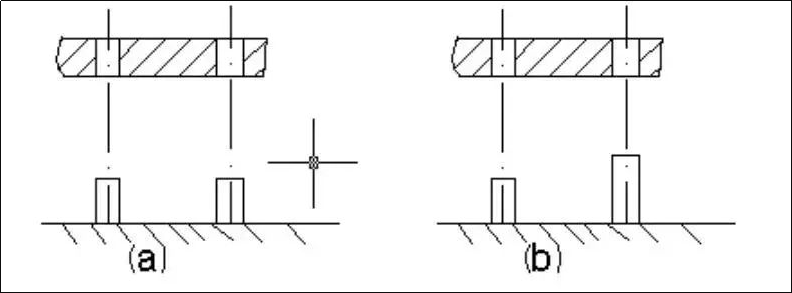
When assembling large boxes, it's important to use several locating pins. It's recommended to make only some of the locating pins the same height, as shown in Figure A, because aligning several pins simultaneously to close the box becomes difficult. Instead, the locating pins should be made of different lengths, as shown in Figure B. This makes it easier to align one locating pin first when closing the box.
3. Correct configuration of large and small gears in gear transmission
To compensate for potential installation errors and ensure the contact line's length and wear during operation, the width of the small gear should generally be 5-10mm larger than that of the large gear. Additionally, because the small gear experiences more wear cycles than the large gear during the same amount of working time, the small gear should have a higher hardness than the large gear to ensure the gear's strength.
4. Screw connections that are frequently disassembled and assembled
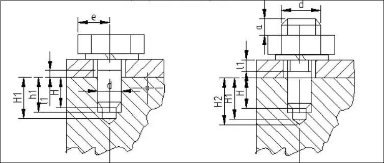
The screw connection is depicted in Figure A. This type of connection involves directly screwing the screw into the threaded hole without using a nut. It is a relatively simple and compact structure, suitable for use in places where bolts cannot be used for connection. However, screw connections are not suitable for locations with significant forces or for frequent disassembly and reassembly.
Frequent disassembly and reassembly can lead to thread wear, potentially resulting in the need to scrap the connected industrial CNC machining parts. In cases where frequent disassembly and reassembly are necessary, stud bolts (studs) can be used for connection, as illustrated in Figure B. The screwing depth is represented as H. When the screw hole is made of steel or has a steel surface, H is approximately equal to d. When the screw hole is made of cast iron, H equals 1.25 to 1.5 times d, and when the screw hole is made of aluminum alloy, H equals 1.5 to 2.5 times d. Additionally, the threaded hole depth H1 is calculated as H plus 2 to 2.5 times the thread pitch (p), and the drilling depth H2 is calculated as H1 plus 0.5 to 1 times d.
5. Intermediate bearing device for high-speed shaft

When installing a coupling on the end of a high-speed rotating shaft, it is important to avoid the structure shown in Figure A. The length of the cantilever should be minimized because longer cantilevers can lead to greater deformation and unbalanced weight. Therefore, when installing the coupling on the cantilever end, it is necessary to reduce the weight of the coupling and ensure that it is positioned close to the bearing.
6. Small diameter deep hole processing

Small-diameter deep holes are challenging to process, resulting in high costs and low efficiency. It is not recommended to design small-diameter lubrication holes for rotating shafts. As illustrated in Figure A, larger holes should be used whenever possible. If needed, different diameters, as demonstrated in Figure B, should be created.
7. The through holes and threaded holes of two interconnected parts do not match;
For example:
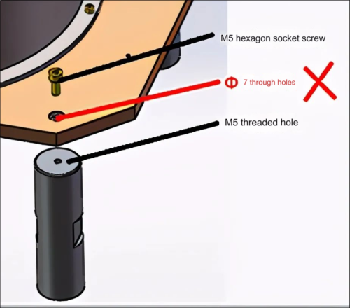
Secondary processing is required to expand the threaded hole and replace the screw during assembly
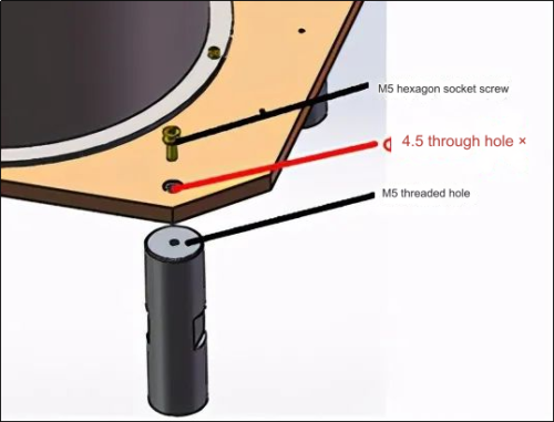
Secondary processing is required to expand the hole during assembly
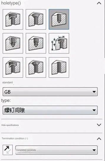
Recommended design with thread clearance holes
8. Ignore the parameters of purchased parts
For example:
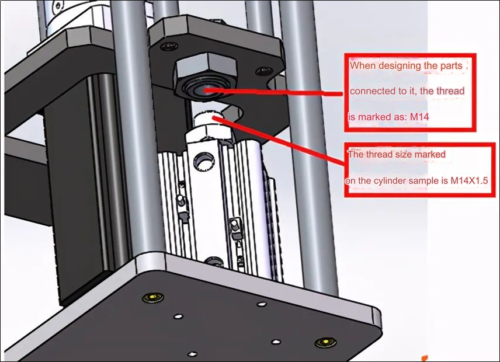
Note: M14 indicates a common coarse thread with a pitch of 2. Therefore, the thread pitch does not match the purchased part during assembly. This case ultimately resulted in the scrapping of the designed connector.
9. The designed parts do not have process fillets and process grooves, and ordinary processing methods cannot complete the processing
For example:
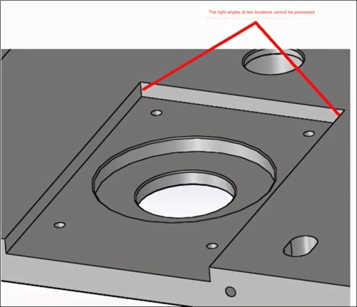
P1
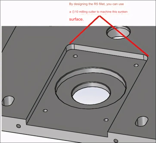
Note: The design shown in Figure 1 does not take into account the process fillet (tools have fillets), and its shape can only be processed by EDM or other special processing methods. Conventional processing methods cannot produce it. If the shape shown in Figure 2 is designed with process fillets, the sinking surface can be milled out first, and then the Φ10 milling cutter can be used to clear the corners. This is convenient for processing and saves costs!
10. The tolerance is not considered when the hole and shaft cooperate with each other, resulting in failure to fit in.
For example:
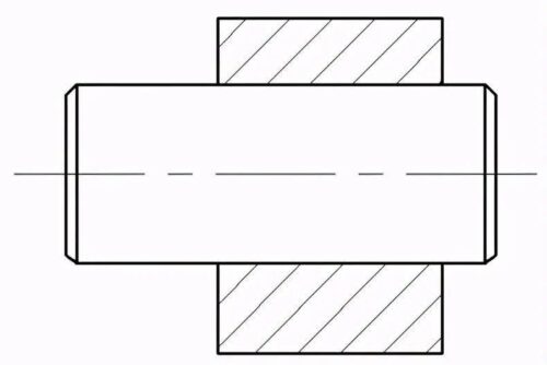
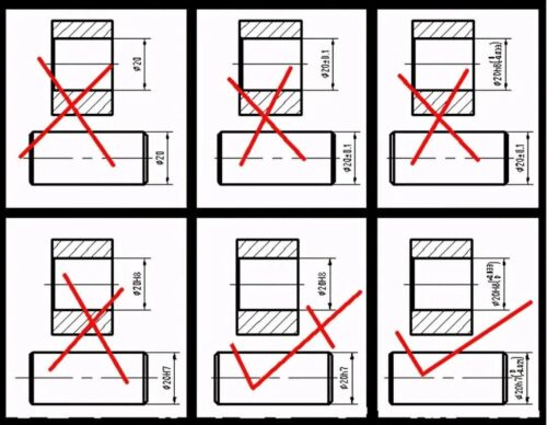
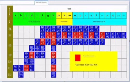
Note: When assembling parts, such as putting a shaft into a hole, installing bearings and bearing seats, or fitting shafts into bearing inner holes, it's important to consider tolerance fits if the hole and shaft diameters are the same. This excludes interference fits, and some transition fits, which are less commonly used. The key principle to remember is that the upper deviation of the shaft diameter must not exceed the lower deviation of the hole diameter. If this happens, the shaft will not fit into the hole. The selection of tolerance fits should be based on the tolerance fits indicated in the figure below. (both in the Mechanical Design Manual and Solidworks).


11. Positioning stoppers were not considered when designing and welding parts, resulting in inconvenience in processing operations.
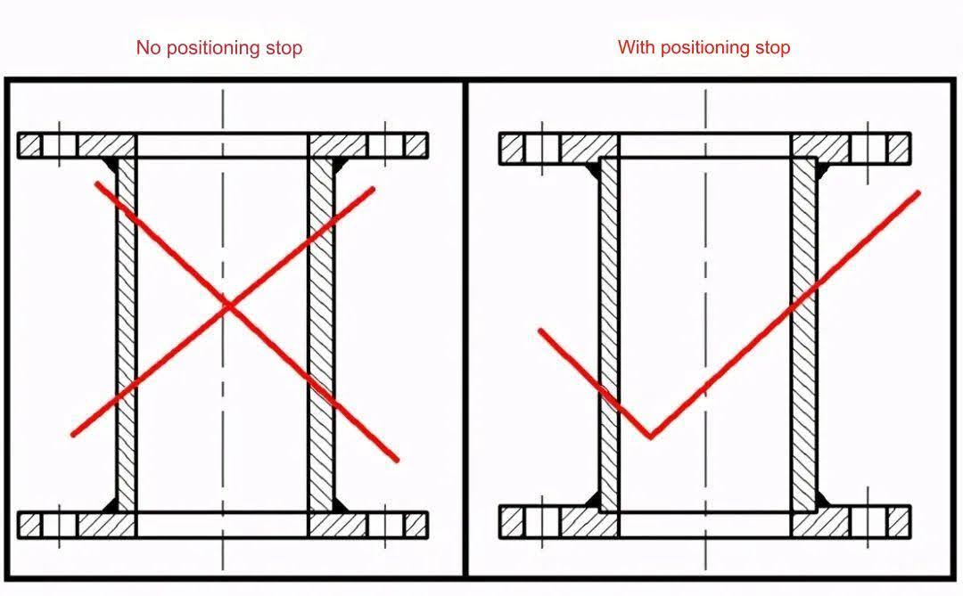
Note: As shown in the figure above, the design without a positioning stop makes it easy to weld the flange and steel pipe off-center (non-concentric) during welding and assembly, which is prone to new problems. With the design of a positioning stop, the welding operator only needs to place the steel pipe into the stop when assembling, and it can be easily and accurately positioned for welding. When designing parts, it is also necessary to consider whether it is convenient for assemblers to assemble, so it is often necessary to consider the design of positioning stop.
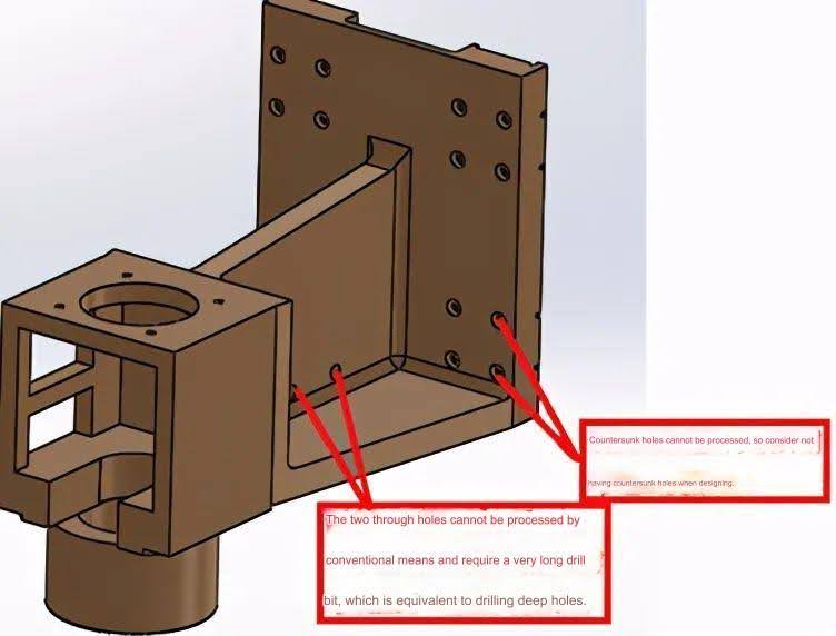
12. When designing parts, it is not considered whether conventional means can be processed.
For example:
13. No processing allowance is left when designing welded parts.
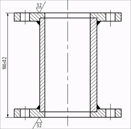
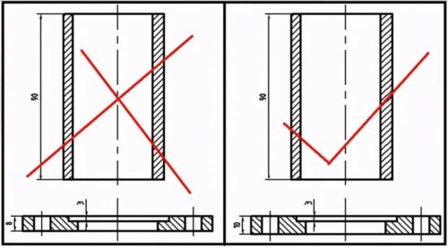
Note: As depicted in the above figure, it is necessary to design a welded part with a required final height of 100mm after processing. The part drawing is as follows. Based on the design in the left figure, the total height before splicing and welding is 100mm. However, due to welding deformation and shrinkage, the total height after welding will be less than 100mm. When the upper and lower flange surfaces are processed to meet the required plane specifications, the final total length will deviate from the original design requirements.
The right figure incorporates the processing allowance in the part drawing design. The total height of the assembled parts is 104mm, allowing for a 2mm processing allowance for both the upper and lower flange surfaces, which is sufficient for processing to the target size. Newcomers often overlook the processing allowance when designing such welded parts, ultimately resulting in the scrapping of parts.
14. During the design of welded parts, welding deformation and welding assembly errors were not taken into account. The installation holes for the welded parts were punched on the parts before welding. However, after welding, it was discovered that the hole positions were incorrect, rendering installation impossible.
For example:
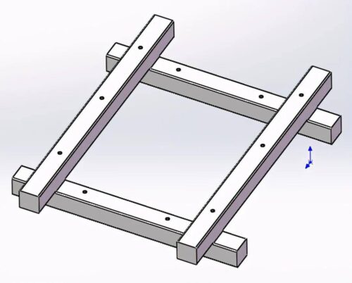
Note: The positioning requirements for several steel bars are very high during welding if the mounting holes on the welded parts are processed when the welded parts are designed. If the welding positioning accuracy cannot be achieved, there is a risk of large errors in the relative position of the mounting holes on the two steel bars, which could lead to installation failure. In principle, the mounting holes of welded parts should be processed after welding. This simplifies welding and ensures the accuracy of the part's position.
15. Surface treatment was not considered when designing parts, such as Q235, 45#, castings, and other rust-prone materials were not surface treated.
Note: Many commonly used materials in mechanical engineering are prone to corrosion and oxidation. When selecting these materials for processing parts, it's important to consider surface treatment as part of the technical requirements. This can include blackening, chrome plating, painting, plastic spraying, sandblasting, and more.
16. Unreasonable selection of part design materials.
Note: There are various types of mechanical engineering materials, each possessing unique properties such as welding performance, anti-corrosion capabilities, thermal conductivity, self-lubricating properties, and heat treatment performance. but newcomers are usually prone to make some typical mistakes in the fast CNC machining process of selecting materials:
1) For stainless steel welded parts, choose 304 (×)
Stainless steel 304L has good welding performance. Under normal use, the company uniformly selects 304L for all stainless steel materials that need to be welded and 304 for stainless steel parts that do not need to be welded.
2) The part depicted requires special processing, such as wire cutting or electric spark, to complete due to its non-metallic material. (nylon 1010) (×)
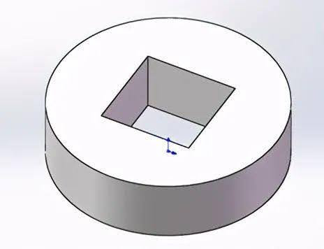
Most non-metallic materials, including nylon 1010, are insulating, which means they cannot be used for wire cutting or EDM due to their insulating properties. When selecting non-metallic materials, factors such as shock absorption, lubrication, and other properties are taken into consideration. Therefore, considering its unique properties, brass H62 is a material selection that is relatively close.
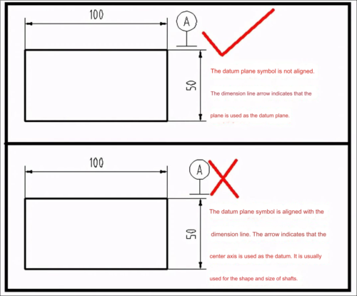
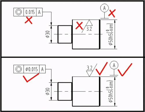
17. The dimension marking is not standardized; for example, the reference plane and reference axis marking are confused.
18. Failure to consider process grooves when designing parts
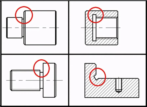
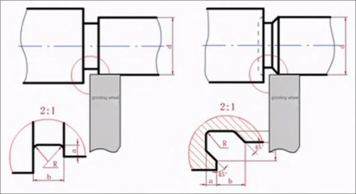
Note: New designers usually do not draw the undercut groove when designing parts. Due to insufficient understanding of the undercut groove, it is easy to ignore it. In fact, it is very important. For example, if there is no undercut groove designed at the root of the internal and external threads, the threaded connector that matches it cannot be screwed to the end face of the root of the thread, which usually makes the designed parts unusable. In addition, when processing high-precision mounting surfaces and stepped shafts, it is necessary to design an overtravel groove at the root of the shaft shoulder. The above figure explains the role of the overtravel groove very well, which allows the processing tool to process the entire cylindrical surface.
If you wanna know more or inquiry, please feel free to contact [email protected]
Anebon has numerous great personnel members who are good at advertising, QC, and working with troublesome dilemmas from the creation course of action for China Supplier. LST-106MY High Cost-Effectiveness CNC machining parts, milling aluminum parts with high-speed customized CNC machining. Anebon, with great passion and faithfulness, is prepared to present you with the best companies and stride forward with you to create a dazzling upcoming event.

