Metal CNC Prototyping: Delivering High-Quality Parts with Precision
30 October 2024
How Die Casting is Revolutionizing the Automotive Industry
5 November 2024The metal-cutting process often generates burrs, which can negatively impact machining accuracy and surface quality. These burrs not only affect the performance of the product but can also lead to accidents. To address the burr issue, a deburring process is typically employed. However, deburring is a non-productive task that increases costs and extends production cycles. Furthermore, improper removal of burrs can result in the scrapping of the entire product, leading to significant economic losses.
This paper provides a systematic analysis of the main factors that influence the formation of burrs during end milling. It also explores methods and techniques for reducing and controlling milling burrs, focusing on both structural design and the entire manufacturing process.
1. The main forms of burrs in end milling
According to the cutting motion-tool cutting edge burr classification system, the burrs generated during end milling can be categorized into several types. These include burrs located on both sides of the main cutting edge, burrs formed in the direction of the side cut, burrs created in the direction of the bottom edge cut, and burrs that arise in both the cutting and feed directions. (see Figure 1).
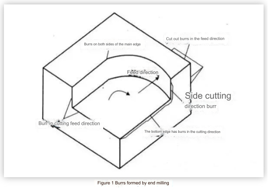
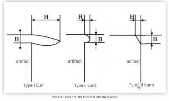
In general, the burrs that form in the cutting direction along the bottom edge tend to be larger and more challenging to remove compared to other burrs. Therefore, this paper focuses specifically on these burrs in the cutting direction of the bottom edge as the main subject of research.
According to the size and shape of the burrs in the cutting direction of the bottom edge in end milling, they can be divided into the following three types: Type I burrs (large in size, difficult to remove, and expensive to remove), Type II burrs (small in size, can be left unremoved or easily removed) and Type III burrs, i.e., negative burrs (as shown in Figure 2).
2. Main factors affecting the formation of end milling burrs
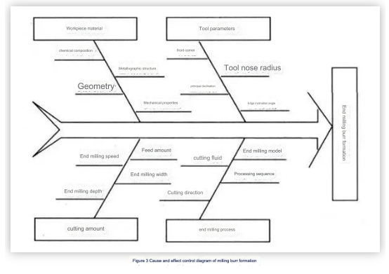
The formation of burrs is a complex process of material deformation influenced by various factors. These factors include the properties of the workpiece material, the geometry of the workpiece, surface treatments, tool geometry, tool cutting trajectory, tool wear, cutting parameters, and the use of coolant.
Figure 3 illustrates a block diagram showing the different factors that affect burr formation in end milling. Under specific milling conditions, the shape and size of end milling burrs are determined by the combined effects of these influencing factors. However, it's important to note that each factor has a varying impact on the formation of burrs.
1. Tool entry/exit
Generally speaking, the burrs generated when the tool is rotated out of the workpiece are larger than those generated when the tool is rotated into the prototype machined parts.
2. Plane cut-out angle
The plane cut-out angle significantly impacts the formation of burrs during cutting in the bottom-edge direction. This angle is defined as the angle between the cutting speed direction (a combination of the tool speed and feed speed) at a specific point on the cutting edge and the direction of the workpiece end face when viewed in a plane that is perpendicular to the milling cutter axis, as the cutting edge rotates out of contact with the workpiece. The direction of the workpiece end face extends from the tool's rotation point to itself.
Test results indicate that the height of the burr changes with variations in cutting depth; specifically, the burr transitions from type I to type II as the cutting depth increases. The minimum cutting depth required to produce type II burrs is referred to as the critical cutting depth, represented by dcr. Figure 4 illustrates the influence of both the plane cut-out angle and cutting depth on burr height when machining an aluminum alloy.
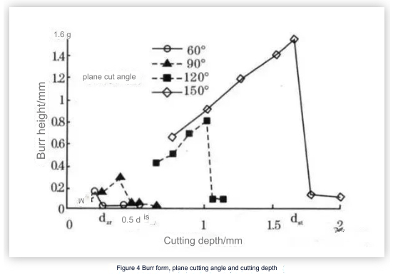
From Figure 4, it is evident that a larger plane cut-out angle results in a greater critical cutting depth. When the plane cut-out angle exceeds 120°, the size of Type I burrs also increases, leading to a larger critical cutting depth required for transitioning to Type II burrs. Consequently, a smaller plane cut-out angle is more favorable for the formation of Type II burrs, as a smaller angle (φ) enhances the support stiffness of the terminal surface, making it less likely for burrs to form.
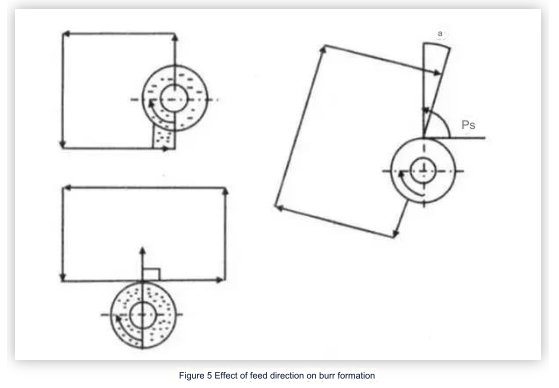
Additionally, the size and direction of the feed speed influence the composite speed (v), which in turn affects the plane cut-out angle and burr formation. Therefore, a higher feed speed and a greater exit edge offset angle (α) result in a smaller φ, which helps in suppressing the formation of larger burrs. (as shown in Figure 5).
3. Tool tip exit sequence EOS
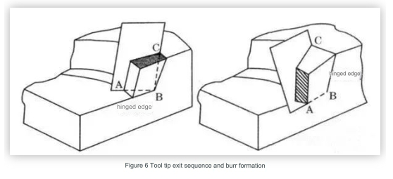
During the end milling process, the size of the burr is largely influenced by the exit sequence of the tooltip. As illustrated in Figure 6, Point A represents a point on the secondary cutting edge, Point C is located on the primary cutting edge, and Point B is the vertex of the tooltip. For the sake of this analysis, we will assume that the tooltip is sharp, meaning that the arc radius of the tooltip is not taken into account.
If the B-C edge exits the workpiece first and the A-B edge follows, the chips will hinge on the machined surface. As milling continues, the chips are pushed out of the workpiece, resulting in a larger bottom edge burr formed in the cutting direction. Conversely, if the A-B edge exits the custom CNC machined parts first and the B-C edge exits later, the chips will hinge on the transition surface and are cut out of the workpiece, leading to a smaller bottom edge burr also forming in the cutting direction.
The test shows that:
① The order of tool tip withdrawal that increases the burr size is ABC/BAC/ACB/BCA/CAB/CBA.
② The results produced by EOS are consistent; however, under the same withdrawal order, the burr size generated from plastic materials is larger than that from brittle materials. The sequence in which the tool tip is withdrawn is influenced not only by the tool's geometry but also by factors such as feed rate, milling depth, workpiece geometry, and cutting conditions. The formation of burrs is affected by a combination of these various factors.
4. Influence of other factors
- Milling parameters, such as milling temperature and cutting environment, can significantly influence the formation of burrs. Key factors like feed speed and milling depth are explained through plane cutting angle theory and tooltip exit sequence (EOS) theory, so we will not revisit those concepts here.
- The better the plasticity of the workpiece material, the easier it is to form type I burrs. When end milling brittle materials, a large feed amount or a steep plane cutting angle can promote the formation of type III burrs (deficient).
- If the angle between the terminal surface of the workpiece and the machined plane exceeds a right angle, the formation of burrs can be reduced due to the increased support stiffness of the terminal surface.
- The use of milling fluid helps extend tool life, reduces tool wear, lubricates the milling process, and thus minimizes burr size.
- Tool wear greatly affects burr formation. As a tool wears, the tooltip arc increases, leading to larger burrs in the tool exit direction. Additionally, type burrs may also form in the tool cut-in direction. This mechanism requires further in-depth research.
- Other factors, such as tool material, also impact burr formation. Under the same cutting conditions, diamond tools are more effective at suppressing burr formation than other types of tools.
5. Basic ways to control the formation of milling burrs
The formation of burrs during end milling is influenced by various factors. This includes not only the specific milling process but also the structure of the workpiece and the geometry of the tool. To minimize the creation of end milling burrs, it is essential to manage and reduce burr generation from multiple aspects.
1.Reasonable Structural Design
The formation of burrs is significantly influenced by the structure of the workpiece. Different workpiece designs can lead to varying shapes and sizes of burrs at the edges after processing. If the material and surface treatment of the workpiece are already determined, then the geometry and edge design of the workpiece become crucial factors in burr formation.
2.Appropriate Processing Sequence
As illustrated in Figure 7, the sequence of processing steps also affects the shape and size of end milling burrs. Various burr shapes and sizes can lead to differing levels of deburring workload and associated costs. Therefore, selecting an appropriate processing sequence is an effective method for reducing deburring expenses.
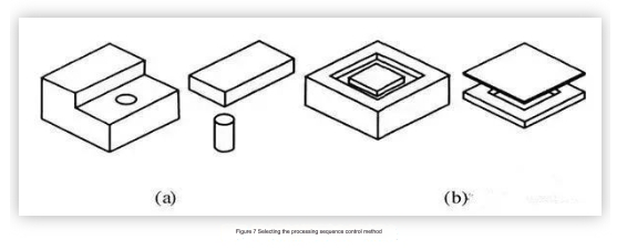
In Figure 8a, if drilling is performed first and then the plane is milled, a significant custom CNC milling burr is produced on the circumference of the hole. However, if the plane is milled first and then drilling is done, only a minor drilling burr is created on the hole's circumference. Similarly, in Figure 8b, when the upper surface is milled first and then the concave contour is machined, the resulting burr is smaller compared to the burr formed when the concave contour is machined first and then the plane is milled.
3.Avoid tool withdrawal
To prevent the formation of burrs, it is essential to avoid tool withdrawal, as this is a primary cause of burr creation in the cutting direction. Typically, burrs produced by a milling cutter when it is withdrawn from the workpiece are larger, while those formed when the cutter is entering the workpiece are smaller. Therefore, minimizing tool withdrawal during processing is advisable.
4.Select an appropriate tool path
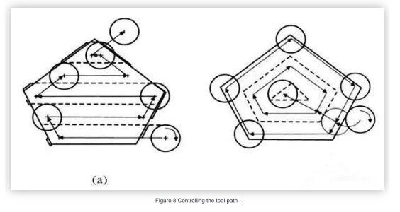
Based on the previous analysis, it is evident that when the plane cutting angle is below a certain threshold, the size of the generated burrs is smaller. The plane cutting angle can be adjusted by modifying the milling width, feed speed (both size and direction), and rotation speed (also in size and direction). By selecting an appropriate tool path, the formation of I-type burrs can be effectively avoided.
5.Select appropriate milling parameters
End milling parameters—such as feed per tooth, end milling width, end milling depth, and tool geometry—significantly influence the formation of burrs.
The creation of burrs during end milling is impacted by several factors, with the primary ones being tool entry and exit, the angle of the cut, the sequence of tooltip exit, and various milling parameters. The final shape and size of the burr result from the combined effects of these factors.
This paper analyzes the main factors that influence milling burrs, starting from the entire process of workpiece structural design to processing technology arrangement, milling volume, and tool selection. It proposes several technologies and methods—including controlling the milling cutter path, selecting an appropriate processing sequence, and enhancing structural design—to suppress or reduce the formation of milling burrs. These suggestions offer a viable technical solution for actively managing burr size, improving product quality, cutting costs, and shortening production cycles in milling operations.
If you wanna know more or inquiry, please feel free to contact [email protected]
Anebon's commission is to serve our buyers and purchasers with the most effective, good quality, and aggressive hardware goods for Hot sale CNC hardware, machined aluminum parts, and CNC rapid prototyping made in China CNC machine Price milling. Furthermore, the company's trust is getting there. Our enterprise is normally at your provider's time.

