How to Choose the Right Machining Services
30 April 2024
Unlocking the Power of Precision Machinery: Maximizing Efficiency and Accuracy in Manufacturing
3 May 20241. Commonly used drawing tools
1. Drawing board:
A drawing board is a rectangular wooden board used to fix drawings. Its requirements:
1) The board surface is flat and smooth;
2) The "leading edge" on the left side should be straight.
Common board specifications:
No. 0 (900mm×1200mm), No. 1 (600mm×900mm), No. 2 (450mm×600mm)
2. T-shaped ruler:
AThe T-shaped ruler consists of a "ruler head" and a "ruler body."Use:
1) Use the drawing board to draw parallel lines.
2) Use the drawing board and triangle board to draw angle lines and vertical lines.
3. Triangular plate:
A set of triangular plates consists of two triangular plates; one is 45°, and the other is 30° (or 60°).
Use:
2) The "leading edge" on the left side should be straight.
2) Use two triangular plates to draw parallel or perpendicular lines to a known straight line.
4. Scale scale is commonly known as "triangular ruler."
4. Scale scale is commonly known as "triangular ruler." There are six commonly used proportion scales, which are used to draw graphics with different size ratios.
Note:) The scale cannot be used as a ruler to draw lines; it can only be used to measure dimensions of different proportions.
5. Curve board Curve board
Is a tool used to draw irregular, non-circular curves (can be used on both sides).
Use:
1) At least 4 points (or four or more points) must match the edge of the curved plate to connect these 4 points (or four or more points);
2) There should be repetition between the two paragraphs.
2. Commonly used drawing supplies
1. Pencils: There are three types of pencils: hard, medium, and soft. Labels for pencils come in 13 different types: 6H, 5H, 4H, 3H, 2H, H, HB, B, 2B, 3B, 4B, 5B, and 6B. The hardest pencil is 6H, the medium hard pencil is HB, and the softest pencil is 6B.
Pencil selection and use:
When drawing manuscripts, it is recommended to use an H or 2H pencil, sharpened into a conical shape. For drawing graphics, a B or HB pencil is recommended, sharpened into a square prism or flat spade shape. It is important to start using the pencil from the unmarked end so that the hard and soft markings of the pencil are retained.
2. Drawing paper: Drawing paper has front and back sides. When drawing, you should use the front side.
Identification method: wipe the eraser over it a few times. The side that is less prone to fluff is the front, or use the observation method to determine that the brighter reflective side is the front.
3. Commonly used drawing instruments
1. Divider: Divider is a tool used to cut off dimensions, bisecting line segments or circles.
Instructions for use: The two-needle tips should be aligned when they are brought together.
2. Compass: A compass is a tool used to draw "circles" or "arcs."
1) Its accessories include steel pin pins, lead pins, duckbill pins, extension rods, etc.
2) How to use it: To draw a large circle with a compass, make sure to use the steel needle end with a "shoulder." The shoulder should be parallel and aligned with the lead core.
Apart from the drawing tools mentioned above, it would help if you also had a ruler, protractor, eraser, picture eraser, knife, sandpaper, tape, and other necessary supplies.
4. Format and format of drawings (GB/T14689—1993)
1. Drawing format
In order to ensure the uniform size of drawings and facilitate the binding, storage, and reduction of drawings, the format of drawings is stipulated as follows:
Drawing format and format (GB/T14689-1993)
Drawing size and code: A0, A1, A2, A3, A4, A5

2. Frame format (frame line)
Drawings must be drawn with thick solid lines before drawing, and the drawn drawings (graphics) should be within the frame line.
There are two formats for frame lines:
Leave no binding margin format ⑵ Leave binding margin format.

3. Title bar and orientation
The direction of the text in the title bar is the direction of viewing the picture. The format, content and size of the title block have been stipulated in the national standard (GB/T10609.1-1989). It is recommended that student drawing assignments adopt the title block format shown in the figure.
4. Additional symbols
1) Centering symbols: For ease of positioning during copying or photography, centering symbols are drawn at the midpoints of each side.
A thick solid line extending approximately 5mm from the edge of the drawing into the drawing frame and with a line width of no less than 0.5mm. When the centering symbol is within the scope of the title block, the part extending into the title block is omitted and not drawn.
2) Direction symbol: To make copying or photography easier, centering symbols are drawn at the midpoint of each side. These symbols are represented by a thick solid line, which extends approximately 5mm from the edge of the drawing into the drawing frame. The line has a minimum width of 0.5mm. If the centering symbol falls within the title block area, the part extending into the title block is omitted and not drawn.

5. Proportion
-
Terminology
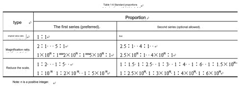
⑴ Proportion: The ratio of the linear dimensions of the graphics in the drawing to the corresponding elements of the actual object.
Original value ratio: The ratio is 1, that is, 1:1.
Magnification ratio: a ratio greater than 1, such as 2:1.
Reduction ratio: a ratio less than 1, such as 1:2.
-
Proportional series
It is recommended to use the preferred ratio series specified in Table 1-2 and then select the ratio series. Regardless of the proportion used, the size values marked on the drawing should represent the actual size of the object. The purpose of marking the size values is to facilitate the viewing of the picture when drawing the pattern. Therefore, the cnc machining parts should be drawn in proportion to their original values as much as possible. In case the parts are too large or too small, the preferred proportions specified in Table 1-2 should be used for drawings.
It is important to note that when drawing the machine parts, whether the drawing is enlarged or reduced, the dimensions should always be marked according to the actual size of the cnc-machined parts, regardless of the proportion used in the drawing.
-
Marking of proportions
1) Mark it in the title bar.
2) Label it below or to the right of the view name. Such as I/2:1, B-B/5:1, etc.
6. Font (GB/T14691-1993)
When creating drawings of machine parts, it's important to use both graphics and text to describe their size, technical requirements, and other important details. The font used in the drawings should be neat, clear, evenly spaced, and well-organized. The size of the font is measured by its height, denoted by "h". The nominal size series for font height are 1.8, 2.5, 3.5, 5, 7, 10, 14, and 20mm. If you need to write characters that are larger than the nominal size, you should increase the font height proportionally to ensure clarity.
- Chinese characters long imitation Song style
- Letters and numbers: Letters and numbers can be written in italics or straight font. Italicized letterheads are tilted to the right at an angle of 75 degrees from the horizontal baseline.
ABCDEFGHIJKLMNOPQRSTUVWXYZ Latin alphabet example
bcdefghijklmnopqrstuvwxy
Ⅰ Ⅱ Ⅲ IV V VI Ⅶ Ⅷ IX Ⅹ Examples of Roman numerals
0 1 2 3 4 5 6 7 8 9 Arabic numerals example
ABCDEFGHIJKLMNOPQRSTUVWXY
Greek letter example:

1) Type A and Type B:
Type A font: stroke width = h/14 (h is the character height)
Type B font: stroke width = h/10 (h is the character height)
2) There are two types: straight and italic (inclined 75o to the right).
7. Drawings (GB/T17450-1998)
Graph lines are various types of lines used in drawing.
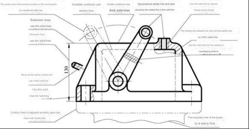
- The form and application of graphs (as shown in Table 1-4)


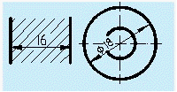
2. Size of drawing lines: Drawing lines are divided into two types: thick and thin. Using the thick line width as a base, the thin line should be half the width of the thick line. Among the various graphs listed in Table 1-4, the width of all graphs except the thick solid line should be half the width of the thick solid line. The recommended series of drawing line widths are 0.18, 0.25, 0.35, 0.5, 0.7, 1, 1.4, and 2? mm. The width of thick lines is generally selected between 0.5~2. Mm according to the size and complexity of the pattern.
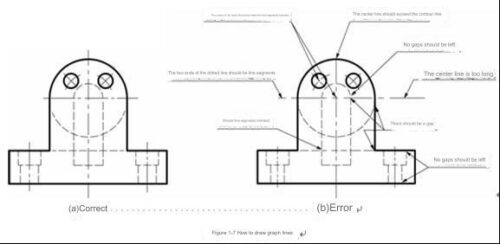
3. How to draw graph lines
⑴In the same drawing, the width of similar drawing lines should be consistent, and the length and spacing of line segments should be approximately equal.
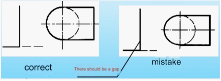
⑵ All kinds of graphs should intersect as line segments, not as points or gaps.
⑶ When the dotted line intersects the solid line, there should be a gap. The dotted arc is tangent to the solid arc, and there should be a gap.
⑷The "point" of the dotted line is a small line segment, not a point. The starting end of the dotted line is a straight segment and should exceed the contour line by 2 to 5 mm.
When drawing the center line of a circle, the center of the circle should be the intersection of the line segments. Both ends of the dotted line should exceed the circle by 2~5mm. The center line of the small circle can be replaced by a thin, solid line instead of a dotted line.
⑹ When a solid line overlaps a dotted line or a dotted line, draw a solid line; when a dotted line overlaps a dotted line, draw a dotted line.
(7) Graph lines should never overlap or be mistaken for words, numbers, or symbols. If such overlap is unavoidable, ensure that the text, numbers, or symbols are clear first. When some graph lines overlap, draw only the first one in the order of thick solid line, dotted line, and dotted line.
Anebon adheres to the tenet "Honest, industrious, enterprising, innovative" to acquire new solutions continuously. Anebon regards prospects and success as personal success. Let Anebon build a prosperous future by hand with brass machined parts and complex titanium CNC parts/ cnc rapid prototyping. Anebon now has a comprehensive goods supply, and the selling price is our advantage. Welcome to inquire about Anebon's products


