Preventative Measures to Avoid Costly Overhauls for Your Machining Spindle
5 August 2024
Define CNC Milling Machine: A Beginner’s Guide to CNC Machining
8 August 2024This is a summary of the industry when summarizing fixture design. However, things still need to be more complex. We have found that there will always be some positioning and clamping in the preliminary design when contacting various schemes. This means that no matter how innovative the scheme is, it will lose its practical significance. It is essential to understand the basic knowledge of positioning and clamping in order to ensure the integrity of the fixture design and processing scheme.
Locator knowledge
1. the basic principle of positioning from the side of the workpiece
When positioning from the side of the workpiece, the three-point principle is the most basic principle, just like support. This is similar to the principle of a brace, called the three-point principle, which is derived from the principle that "three points that are not on the same line determine a plane." Out of the 4 points, 3 points can determine one face, so a total of 4 faces can be determined, but no matter how you position it, it isn't easy to make the 4th point in the same plane.
3-point principle
When using four fixed-height positioners, only three points at a certain place can contact the workpiece, and the remaining fourth point may not make contact with the workpiece.
As a result, when configuring the positioner, it's common to use three points as the reference and to increase the distance between these three points as much as possible.
It's also important to confirm the direction of the applied processing load when configuring the positioner. The direction of the processing load is also the direction of the tool holder/tool movement. Configuring the positioner at the end of the feed direction can directly affect the overall accuracy of the workpiece.
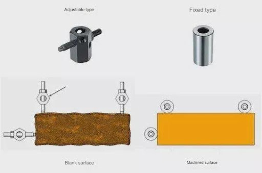
Generally, a bolt-type adjustable positioner is used when positioning the workpiece blank surface, and a fixed type (with the workpiece contact surface ground) positioner is used when positioning the workpiece processing surface. For example, when using four fixed-height positioners, only 3 points at a certain place can contact the workpiece, and the remaining 4th point is likely to not contact the workpiece.
When setting up the positioner, it's common to use three reference points, and the distance between these points should be maximized.
It's also important to determine the direction of the processing load before configuring the positioner. The direction of the processing load is the same as the movement direction of the tool holder/tool. Optimizing the positioner at the end of the feed direction can significantly impact the overall accuracy of the workpiece.
Typically, a bolt-type adjustable positioner is used when positioning the workpiece blank surface, and a fixed-type positioner (with the workpiece contact surface ground) is used when positioning the workpiece processing surface.
2. Basic principles of positioning from the workpiece hole
When positioning a workpiece using a hole created in a previous step, it is necessary to use a pin with the appropriate tolerance for positioning. By aligning the accuracy of the workpiece hole with the accuracy of the pin shape and combining them within the matching tolerance, the positioning accuracy can meet the actual requirements.
Additionally, straight pins are typically used for one side of the positioning, and diamond pins for the other side. This makes it easier to install and remove the workpiece and reduces the likelihood of the workpiece getting stuck on the pins.
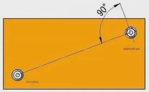
use pin positioning
It is possible to adjust the fit tolerances to make both pins use straight pins for precise positioning. However, for more accurate positioning, it is usually most effective to use a straight pin and a diamond pin.
When using a straight pin and a diamond pin, the diamond pin (contacting the workpiece) is typically positioned at a 90° angle perpendicular to the line between the straight pin and the diamond pin. This arrangement ensures that it is angular in relation to the direction of rotation of the workpiece.
Knowledge of clamps
1. The classification of clamps
According to the clamping direction, it is generally divided into the following categories:
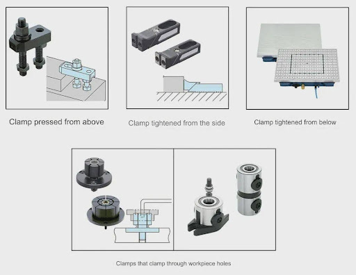
Next, let's take a look at the characteristics of various clamps.
1. A clamp that is pressed from above
When clamping a workpiece, it's important to consider clamping it from the top to minimize deformation and ensure stable machining. Utilizing a manual mechanical fixture, such as a "Loose Leaf Clamp," which consists of a pressure plate, stud bolt, jack, and nut, is a common method for clamping from above the workpiece.
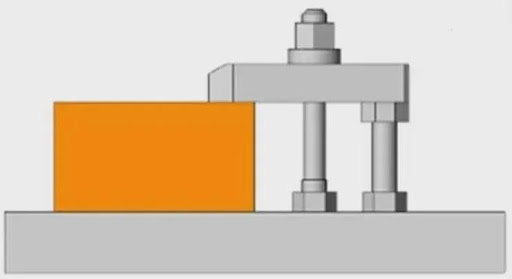
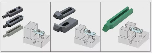
In addition, depending on the shape of the workpiece, you can select a pressure plate of different shapes for a variety of workpieces.
The relationship between torque and clamping force during clamping of a loose leaf clamp can be calculated by the propulsion force of the bolt.
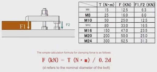
In addition to the loose leaf clamps, there are similar clamps as follows.
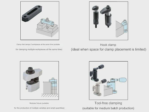
2. A clamp that is clamped from the side
The most stable method originally for clamping the workpiece was from above, which also resulted in the smallest machining load. However, if it's not possible to clamp from the top, such as when machining the top of the workpiece, or if top clamping isn't suitable, then clamping from the side can be an option. When clamping from the side, there will be a floating force, and it's important to consider how to eliminate this force when designing the fixture.

The clamp that is clamped from the side also has a force that slopes downward while generating thrust on the side, as shown in the figure above, and this clamp can effectively prevent the workpiece from floating.
Clamps that clamp from the side also have similar clamps.
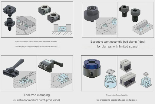
3. Tighten the clamp of the workpiece from below
When machining the upper surface of a thin plate workpiece, it is important to consider the clamping method. Clamping the workpiece from above or compressing it from the side is not practical. Instead, the reasonable clamping method is to tighten the workpiece from below.
For iron workpieces, a magnet-type clamp can be used for below-tensioning. Vacuum suction cups can be used for metal workpieces made of non-ferrous materials.
In both cases, the clamping force is determined by the contact area between the workpiece and the magnet or vacuum gripper. When 5-axis CNC machining small workpieces with heavy loads, using this clamping method will yield better machining results.

In addition, when using magnets or vacuum cups, the contact surface between the magnet and the vacuum cup needs to be smoothed to ensure safety and normal function.
4. A clamp that uses holes to clamp
When using a 5-axis machining machine for multi-sided simultaneous machining or mold machining, it is generally appropriate to use hole clamping. This helps prevent jigs and tools from affecting the CNC machining services. Compared with clamping from the top of the workpiece or from the side, the hole clamping method creates less load on the workpiece and can effectively minimize workpiece deformation.
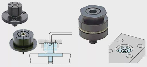
Machining is carried out directly using holes
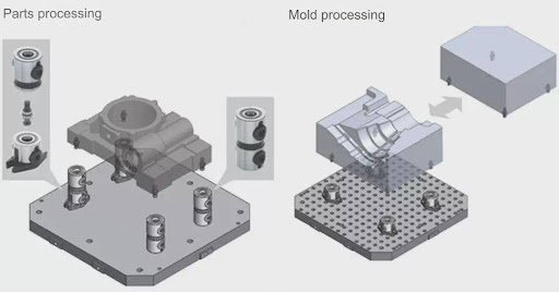
Set up a rivet for clamping
2. Pre-clamping
The preceding information primarily focuses on workpiece clamping using a clamp and how to enhance its operability. The use of pre-clamping is also essential. When the workpiece is positioned vertically on the base, it may fall due to gravity. Therefore, it is necessary to manually operate the clamp while securing the workpiece.
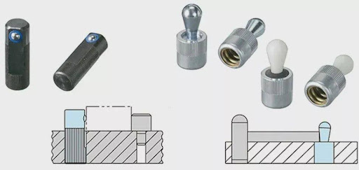
Pre-clamping
If the workpiece is heavy or if multiple workpieces are clamped simultaneously, the operability will be greatly reduced, and the clamping time will be long. In such cases, using this spring pre-clamping product can keep the workpiece in a stationary state while operating the clamp, significantly improving operability and reducing workpiece clamping time.
3. Precautions when choosing a clamp
When using multiple types of clamps with the same tooling, it's important to ensure that the tools used for clamping and unclamping are consistent. For instance, in the left figure, using a variety of tool wrenches during clamping increases the overall load on the operator and extends the clamping time for the workpiece. However, in the right figure, using uniform tool wrenches and bolt sizes is more convenient for on-site operators.

Operability of CNC prototype clamping
In addition, when configuring the clamp, it is necessary to take into account the operability of the workpiece clamping as much as possible. If the workpiece needs to be angled when clamping, the operability could be more convenient, and this situation needs to be avoided when designing the fixture tooling.
If you want to know more or inquiry, please feel free to contact [email protected] With a significant share in the global market for CNC machining parts and machining parts, Anebon has strong economic strength and offers excellent sales service. The company has established a faith, friendly, and harmonious business relationship with customers in different countries, including Indonesia, Myanmar, Southeast Asian countries, and European, African, and Latin American countries.

