How Die Casting is Revolutionizing the Automotive Industry
5 November 2024
How Sheet Metal Fabrication Shapes Industries
8 November 2024Drill bits are the most commonly used tools for creating holes in mechanical manufacturing. They play a crucial role, especially in processing holes in components like cooling devices, tube sheets of power generation equipment, and steam generators. Their extensive application highlights their importance in the industry.
1. Drilling characteristics
Drill bits typically have two primary cutting edges. During operation, the drill bit cuts while it rotates. The rake angle of the drill bit increases progressively from the central axis to the outer edge. As you move closer to the outer circle, the cutting speed of the drill bit rises, while it decreases toward the center. At the center of the drill bit’s rotation, the cutting speed is zero.
The chisel edge of the drill bit is located near the central axis of rotation. It has a large negative rake angle, minimal chip space, and lower cutting speed, which leads to increased axial resistance. If the chisel edge is ground to type A or type C, as indicated in DIN1414, and if the cutting edge near the central axis is designed with a positive rake angle, the cutting resistance can be reduced, significantly enhancing cutting performance.
Drill bits can be categorized into various types based on the shape, material, structure, and function of the workpiece. Examples include high-speed steel drill bits (such as twist drills, group drills, and flat drills), solid carbide drill bits, indexable shallow hole drills, deep hole drills, nesting drills, and replaceable head drill bits, among others.
2. Chip breaking and chip removal
When a drill bit operates, it cuts through a narrow hole, and the resulting chips need to be expelled through the grooves of the drill bit. The shape of these chips significantly impacts the cutting performance of the drill bit. Common chip shapes include flake chips, tubular chips, needle chips, conical spiral chips, ribbon chips, fan-shaped chips, and powder chips.
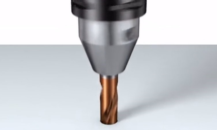
The key to drilling processing - chip control
When the shape of the chips produced during drilling is inappropriate, several issues can arise:
- Fine chips can block the cutting edge, which affects drilling accuracy, reduces the drill bit's lifespan, and may even lead to breakage (examples include powdery chips and fan-shaped chips).
- Long chips can wrap around the drill bit, obstructing operation. This can cause the drill bit to break or prevent cutting fluid from entering the hole (examples include spiral chips and ribbon chips).
How to solve the problem of inappropriate chip shape:
- To improve chip breaking and removal, you can employ various methods either individually or in combination. These methods include increasing the feed rate, using intermittent feeding, grinding the chisel edge, and installing a chip breaker. Implementing these strategies can help eliminate problems caused by chips.
- Consider using a specialized chip-breaking drill for hole drilling. For instance, adding a specifically designed chip-breaking edge to the drill bit's groove will help break the chips into smaller, more manageable debris. This debris can then be smoothly discharged along the groove, preventing any clogging. As a result, this innovative chip-breaking drill offers a much smoother cutting experience compared to traditional drills.
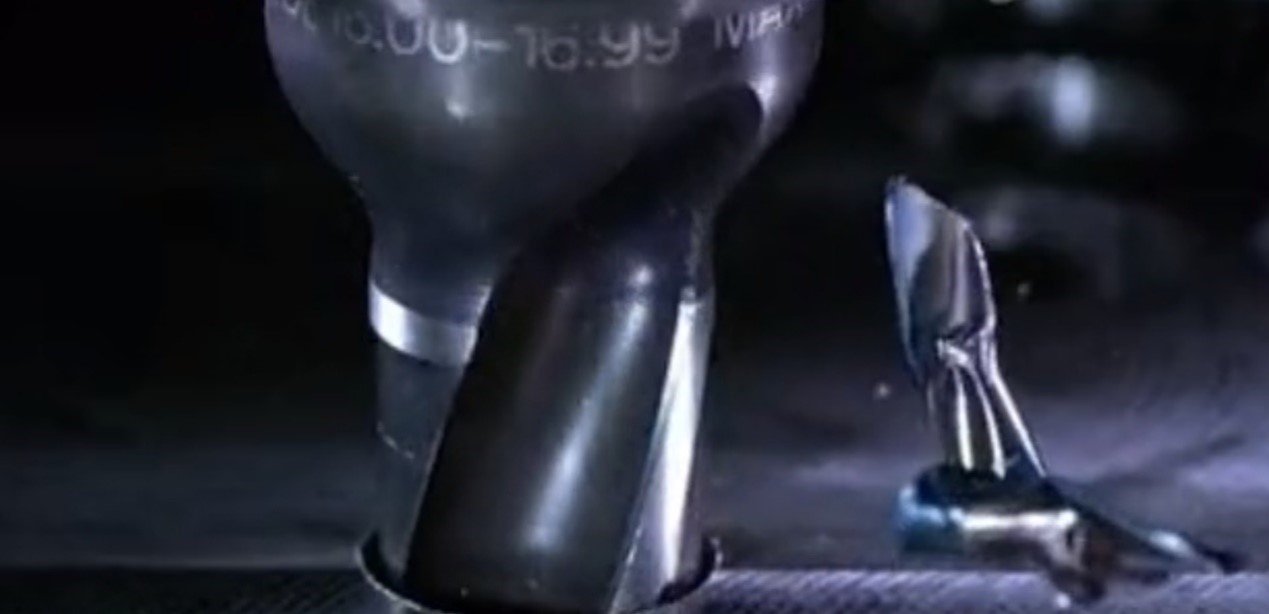
The short-crushed iron chips enhance coolant flow to the drill tip, which improves heat dissipation and cutting performance during CNC machining turning. Additionally, the newly integrated chip-breaking edge extends throughout the drill's groove, allowing it to maintain its shape and functionality even after repeated sharpening.
Beyond these functional improvements, it's important to note that this design enhances the rigidity of the drill body and significantly increases the number of holes that can be drilled before requiring a single grinding operation.
3. Drilling accuracy
The accuracy of a hole is influenced by several factors, including hole diameter, positional accuracy, coaxiality, roundness, surface roughness, and the presence of burrs.
Factors that affect the accuracy of a drilled hole include:
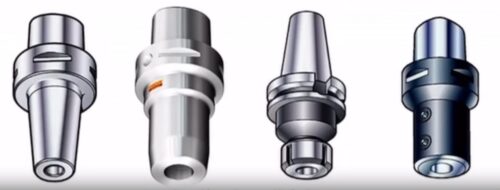
- The clamping accuracy and cutting conditions of the drill bit, which encompass elements such as the tool holder, cutting speed, feed rate, and cutting fluid.
- The size and shape of the drill bit, including the length of the bit, the design of the cutting edges, and the profile of the drill core.
- The shape of the custom CNC machining parts, taking into account aspects like the contour of the hole, its dimensions, thickness, and clamping state.
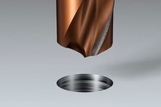
Hole expansion
Hole expansion occurs due to the swinging motion of the drill bit during the drilling process. The movement of the tool holder has a significant impact on both the diameter of the hole and its accuracy in positioning. Therefore, if the tool holder shows considerable wear, it should be replaced promptly.
When drilling small holes, measuring and adjusting the swinging motion can be challenging. In these cases, it is advisable to use a coarse-shank small-diameter drill that ensures good coaxiality between the blade and the shank.
Additionally, when using a reground drill bit, a decrease in hole accuracy is often due to the asymmetry of the back shape. To achieve better results, controlling the height difference of the blade can effectively limit both the amount of cutting and the expansion of the hole.
Hole roundness
Due to the vibration of the drill bit, the shape of the drilled hole can easily become polygonal, resulting in rifling-like lines on the walls. Common polygonal shapes are typically triangles or pentagons. Triangular holes form because the drill has two centers of rotation while drilling, which vibrate at a frequency of 600 revolutions per minute. This vibration primarily arises from unbalanced cutting resistance. As the drill completes one rotation, the roundness of the processed hole is compromised, leading to unbalanced resistance during the subsequent cutting rotation. This repetitive vibration, with a slight phase shift, causes rifling lines to appear on the hole wall.
When the drilling depth reaches a certain level, the friction between the edge of the drill bit and the hole wall increases, helping to dampen the vibration. As a result, the rifling disappears, and the roundness of the hole improves. At this point, the hole assumes a funnel shape when viewed in cross-section. Similarly, pentagonal and heptagonal holes can also form during cutting due to this phenomenon.
To address these issues, it is essential to control factors such as chuck vibration, differences in cutting-edge height, and asymmetry in the back and blade shapes. Additional measures to improve drill rigidity, increase the feed per revolution, reduce the back angle, and sharpen chisel edges should also be implemented.
Drilling on inclined and curved surfaces
When the cutting or drilling surface of a drill bit is inclined, curved, or stepped, the positioning accuracy tends to be poor. This is due to the fact that the drill bit cuts radially on one side, which can lead to a reduced tool life.
To enhance positioning accuracy, the following measures can be taken:
- First, drill a center hole.
- Use an end mill to create the hole seat.
- Select a drill bit with excellent cutting performance and rigidity.
-
Reduce the feed speed.
Burr treatment
When drilling, burrs can form at both the entrance and exit of the hole, particularly when working with tough materials and thin plates. This occurs because, as the drill approaches the material, plastic deformation takes place. During this CNC machining process, the triangular section that should be cut by the drill's outer cutting edge gets deformed and bends outward due to the axial cutting force. Additionally, the chamfer of the drill's outer edge and the edge of the land cause this deformed section to curl, resulting in the formation of a curled edge or burr.
4. Drilling processing conditions
General drill product catalogs include a "Basic Cutting Quantity Reference Table" organized by processing material. Users can refer to this table to select the appropriate cutting conditions for drilling. However, the suitability of these cutting conditions should be evaluated comprehensively, taking into account test cuts, processing accuracy, efficiency, drill lifespan, and other relevant factors.
1. Drill life and processing efficiency
To evaluate the proper use of a drill, it is essential to consider both the life of the drill and its processing efficiency, provided that the technical requirements of the workpiece are met. Drill life can be assessed based on cutting distance, while processing efficiency can be measured using feed speed.
For high-speed steel drills, drill life is significantly influenced by rotation speed, with less impact from feed per revolution. Therefore, to enhance processing efficiency without compromising drill life, it is advisable to increase the feed per revolution. However, caution is required: if the feed per revolution is too high, the chips produced may become too thick, making them difficult to break. It is necessary to determine the appropriate range of feed per revolution for smooth chip breaking through trial cutting.
In the case of carbide drills, the cutting edge features a larger chamfer directed towards the negative rake, resulting in a smaller allowable range of feed per revolution compared to high-speed steel drills. Exceeding this range during processing will lead to a reduction in drill life. Additionally, the heat resistance of cemented carbide drills is greater than that of high-speed steel drills, making rotation speed less impactful on the life of the drill. Consequently, increasing the rotation speed can be an effective strategy to enhance the processing efficiency of cemented carbide drills while still ensuring their longevity.
2. Reasonable use of cutting fluid
Drill cutting occurs in narrow spaces, making the choice of cutting fluid and application method crucial for both the lifespan of the drill and the accuracy of the hole being processed. Cutting fluids generally fall into two categories: water-soluble and non-water-soluble.
Non-water-soluble cutting fluids provide excellent lubrication, wettability, and anti-adhesive properties, in addition to offering protection against rust. On the other hand, water-soluble cutting fluids deliver superior cooling performance, produce no smoke, and are non-flammable. Due to environmental considerations, the use of water-soluble cutting fluids has significantly increased in recent years. However, if the dilution ratio of a water-soluble cutting fluid is incorrect or if the fluid deteriorates, it can considerably reduce the tool's service life, so careful usage is essential.
Regardless of the type of cutting fluid—whether water-soluble or non-water-soluble—it is vital that the fluid effectively reaches the cutting point during operation. Furthermore, factors such as the flow rate, pressure, number of nozzles, and cooling method (internal or external) must be meticulously controlled to ensure optimal performance.
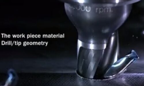
5. Drill bit resharpening Drill bit resharpening judgment
The judgment criteria for drill bit resharpening are:
- Use cutting-edge technology, including chisel edges and optimized edge surfaces.
- Ensure dimensional accuracy and appropriate surface roughness for processed holes.
- Observe the color and shape of the chips produced.
- Monitor cutting resistance through indirect indicators such as spindle current, noise, and vibration.
- Track the quantity of processing done, among other factors.
In practical applications, it is essential to establish accurate and convenient discrimination criteria tailored to specific circumstances based on the indicators mentioned above. When using the wear amount as the discrimination criterion, the goal should be to determine the optimal re-sharpening period that balances performance and cost-effectiveness. Given that the primary grinding areas of the drill bit are the back of the head and the transverse edge, excessive wear can lead to longer grinding times and larger grinding amounts. This results in fewer re-sharpening opportunities, ultimately reducing the total service life of the tool (total service life = tool life after re-sharpening × number of re-sharpening cycles).
Alternatively, if the dimensional accuracy of the processed hole is used as the discrimination criterion, factors such as hole expansion and non-straightness should be assessed with column gauges or limit gauges. If the measurements exceed the control values, immediate re-sharpening is recommended. When cutting resistance serves as the discrimination criterion, an automatic shutdown method should be implemented to trigger when the set limit value (e.g., spindle current) is surpassed. In cases where processing quantity limits are managed, it is advisable to integrate the above discrimination criteria to set comprehensive guidelines.
Drill bit sharpening method
When re-sharpening a drill bit, it is best to use a specialized machine tool or a universal tool grinder. This is crucial for maintaining the drill bit's service life and processing accuracy. If the original shape of the drill bit is in good condition, it can be reground to match that shape. However, if there are defects in the original drill shape, the rear geometry can be improved, and the cutting edge can be reshaped based on its intended use.
The following points should be noted when sharpening:
- Prevent overheating to avoid reducing the hardness of the drill bit.
- Remove any damage on the drill bit, especially any damage to the edge of the blade.
- Ensure that the drill shape is symmetrical.
- Be careful not to damage the cutting edge during sharpening, and remember to remove burrs after sharpening.
5. For carbide drill bits, the sharpening shape significantly impacts performance. The drill bit shape provided by the manufacturer is based on scientific design and rigorous testing, making it the optimal shape. Therefore, you should generally maintain the original blade shape when re-sharpening.
If you want to know more or inquiry, please feel free to contact [email protected]
Anebon is able to supply high-quality merchandise, competitive selling prices, and the finest customer support. Anebon's destination is "You come here with difficulty, and we supply you with a smile to take away" for CNC custom machining and Die-casting service. Now, Anebon has been considering all specifics to ensure each product or service is contented by our buyers.

